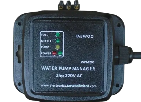
WPM201: Water pump manager
The WPM201 is a cutting-edge electronic device that delivers fully automated refilling operation, ensuring seamless functionality while safeguarding your water pump investment for years to come.
Installation Requirements for WPM201
To establish a connection between the WPM201 and the water level sensor at the overhead tank, a 2-pair link cable of sufficient length is mandatory.
Determining Link Cable Length
Prior to placing an order, it is essential to determine the optimal cable route between the overhead tank and the existing manual water pump controller. Measure this distance and select a link cable that is 1-2 meters longer than the measured route.
Ordering Procedure
During the checkout process, ensure that you select the corresponding link cable length as an accessory to your WPM201 order. This will guarantee a seamless installation and proper functionality of the system.
Installation and Commissioning Guide for WPM201 Water Pump Manager
Introduction
The WPM201 is designed to automate existing manual water pump installations. This guide outlines the step-by-step installation and commissioning process for seamless integration.
What is included in the pack?
- WPM201 main unit.
- 2 nos. 8mm screw and Fitcher pegs
- Water sensor module
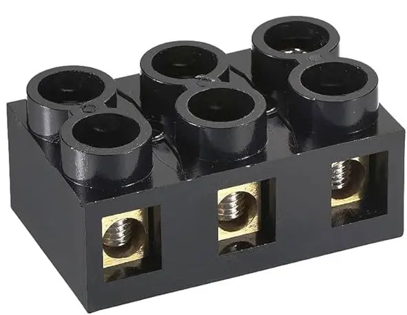
- 3-terminal terminal strip
- 2 nos. 25mm x 2mm screws
Installation Steps
Before embarking on the installation, in addition to the WPM201 package, get to hand the following:
- Determine and purchase the required length of the connecting cable that will run between the tank's top and the installation location of the WPM201 unit.
- Tools:
- Sharp point for marking on plastic
- Cutter plier
- Wire stripper
- Drill or narrow point tipped soldering iron to make holes in plastic
- Flat or star head terminal screwdriver
- Multimeter set as Ohmmeter.
- Accessories needed for the installation
- Electrical insulation tape
- 150mm cable ties
- Wall clips
A. Sensor Assembly Installation
The sensor assembly is composed of 3 wires of different lengths, each terminated at one end by a stainless-steel ball. The steel-balls determine the sensing levels in the overhead tank.
Step 1: Install the 3-pin terminal strip connector on a shoulder of the tank.
- Identify the inlet pipe into the tank, DO NOT install the connector on either the inlet shoulder or the one directly opposite it
- To install the terminal strip connector, select the shoulder either side of the inlet shoulder as convenient.
- Place the terminal strip on the chosen shoulder with the connections aligning with the axis of the shoulder.
- Use a sharp point to mark the position of the two fixing holes on the shoulder.
- Punch or drill 2 nos. 1.5mm holes for fixing the 3-terminal strip connector to the shoulder.
- Secure the terminal strip firmly to the tank shoulder using the provided 25mm x 2mm screws.
Step 2: Install the Sensor Wires
- On the neck of the tank, just below the cap thread and on the same side as the terminal strip, drill three 2mm-diameter holes spaced approximately 12mm apart, almost imitating the terminals on the connector.
- Select the sensor wires by length, starting with the shortest:
- Select the shortest sensor wire, pass its free end from within the tank through the first hole counting from the left.
- Peel this wire about 5mm on the free end outside the tank to reveal the conductor and secure into Terminal 1 of the connector (from left)
- Select the next sensor wire, pass its free end from within the tank through the second hole counting from the left.
- Peel this wire about 5mm on the free end outside the tank to reveal the conductor and secure into Terminal 2 of the connector (from left)
- Select the last (longest) sensor wire, pass its free end from within the tank through the third hole counting from the left.
- Peel this wire about 5mm on the free end outside the tank to reveal the conductor and secure into Terminal 3 of the connector (from left)
- Quality Control checks
- Tuck firmly at each wire at the connector end to ensure that it is firmly in place and will not easily come off the terminal.
- Redo until achieved.
- Using a multi-meter set to Ohm's measurement, ensure there is continuity between the terminals of the connector and their corresponding steel balls
- Finally, let the ball ends drop freely in the tank and ensure that:
- the steel ball of terminal 1 hangs freely about 100mm below the neck of the tank indicating the FULL sensing level.
- the steel ball of terminal 2 hangs freely about 900mm below the neck of the tank indicating the threshold sensing level for triggering refilling.
- the steel ball of terminal 3 must hangs freely in the tank below the ball of terminal 2.
- This completes the installation of the sensor wires on the overhead tank.
- Check the connection between the sensor wires and the roll of the 3-core or 2-pair 0.9mm2 connecting cable:
- If you are using the 2-pair 0.9mm2 cable, without uncoiling the cable, prepare the 4 wires on one end of the cable:
- connect both tip conductors (white) to Terminal 3 of the sensor connector.
- connect the blue conductor to Terminal 1
- connect the orange conductor to Terminal 2
- If instead, you are using a 3-core cable, without uncoiling the cable, prepare the 3 wires on one end of the cable:
- connect the brown conductor to Terminal 1
- connect the green/yellow stripes conductor to Terminal 2 and
- connect the blue conductor to Terminal 3
- Tuck firmly on the 3 connections in turn to confirm that they are securely connected, improve on the connections until satisfied.
- Check the continuity of the connections between the free end of the connecting cable and the steel balls:
- raise Terminal 1's steel ball from the tank and check continuity between it and the free end of its connected wire.
- raise Terminal 2's steel ball from the tank and check continuity between it and the free end of its connected wire.
- raise Terminal 3's steel ball from the tank and check continuity between it and the free end of its connected wire.
Step 3: Install the WPM201 Main Unit
Positioning the WPM201 Main Unit:
- The WPM201 is designed to be installed adjacent to a wall-mounted water pump controller.
- Position the WPM201 on the left side of the water pump controller close enough for the power cable to reach deep into the controller box.
Preparation Steps:
1. Isolate the water pump controller from the mains power by switching it off at its associated gear switch.
2. Remove the cover of the water pump controller box.
Cable Routing:
3. Drill a 10mm diameter hole on the side wall of the water pump controller box, just below the terminal strip.
4. Feed the WPM201's power cable through the hole, inserting it to reach the middle of the controller box.
5. Inside the controller box, approximately 10mm from the entry point, mark the power cable. The insulation on the power cable should be removed at this point to reveal the three cores of the cable.
Mounting the WPM201 Unit:
6. Mark the positions for the four mounting holes on the wall where the WPM201 will be installed.
7. Drill four holes and insert 8mm fischer plugs into each.
8. Secure the WPM201 in place using the provided 8mm screws.
Cable Preparation:
9. At the previously marked position on the power cable, strip the insulation to expose the three inner cores.
The RED is the power Live to the WPM201
The BLUE is the Neutral
The YELLOW is the switched power
Ensure all connections are made securely and in compliance with local electrical codes before proceeding with the installation.
C. Link Cable Installation
1. Use a rope to determine the optimal route for the 2-pair 0.9mm2 telephone cable between the storage tank and the water pump controller box location. Purchase the length of link cable a couple of meters longer than the length determined using the rope.
2. Lay the cable, avoiding objects and potential damage.
3. Ensure no joints are required; if necessary, use a longer cable.
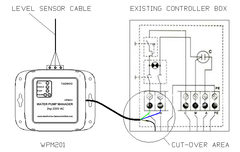
D. Cut-Over Connections
1. Switch off power to the water pump controller box.
2. Confirm zero voltage between pins 1 and 2.
3. Introduce the WPM201 power cable and connect:
- L (Red/brown) to Pin 1.
- N (Blue/black) to Pin 2.
- Switch output wire (Green/Yellow) to Pin 1.
E. Level Sensor Cable Connection
1. Cut and peel the level sensor cable.
2. Connect wires to WPM201 terminals:
- Black wire pair to pole 1.
- Brown wire to pole 2.
- White wire to pole 3.
F. Commissioning
1. Verify all connections are secure.
2. Switch on power to the controller box.
3. Observe LED indicators for system status:
- Red: Power outside safe operation range.
- Green: Power within safe operation range.
- Middle and full LEDs: Tank full, pumping stopped.
- Automatic panic mode: Pumping resumes to fill tank.
Troubleshooting
If issues arise, review the installation instructions carefully and re-check connections.
Important Safety Considerations
- Ensure proper electrical safety measures are taken during installation.
- Verify compatibility with existing system components.
By following this guide, you'll successfully install and commission the WPM201, ensuring efficient and automated water pump management.